
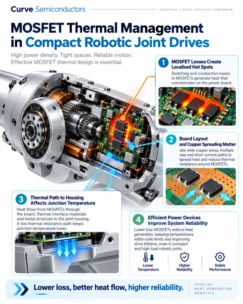

Compact robotic joints combine several demanding engineering problems in one small volume: high motor current, rapid acceleration and braking, limited airflow, tight PCB area and a metal structure that must carry both mechanical load and heat.
That makes the power MOSFET more than a switching component. Its losses, package, gate-drive requirements and thermal path can influence joint temperature, available torque, power density and reliability.
The right question is therefore not simply:
Which MOSFET has the lowest RDS(on)?
A better question is:
Which MOSFET remains efficient, controllable and thermally safe across the real motion profile of the joint?
1. Start with the real joint operating envelope
Before comparing devices, define the electrical and mechanical conditions that the power stage will actually see.
| Design input | What to capture |
|---|---|
| DC bus | Nominal, maximum and transient voltage |
| Motor current | RMS, average, peak and stall current |
| Motion profile | Acceleration, holding torque, reversal and braking |
| Switching frequency | Normal and worst-case PWM frequency |
| Gate drive | Actual VGS and driver source/sink capability |
| Thermal environment | Housing temperature, airflow and nearby heat sources |
| Fault behaviour | Stall, jam, overcurrent, regenerative events and shutdown |
| Mechanical path | How the PCB and package connect thermally to the joint housing |
Robotic joints are often highly dynamic. A short acceleration pulse may produce very different semiconductor stress from steady motion, while regenerative braking can reverse current flow and change switching conditions.
The MOSFET therefore has to be evaluated against time-dependent current and voltage, not only average power.
2. Hot RDS(on) determines real conduction loss
For a motor phase or bridge leg, a first-order conduction estimate is:
Pcond ≈ Irms² × RDS(on)
But the useful value is the resistance at the actual gate voltage and expected junction temperature.
MOSFET resistance rises as the junction gets hotter. In a compact actuator, this creates an important feedback loop:
higher current → higher loss → higher junction temperature → higher RDS(on) → still higher loss
This is why room-temperature headline resistance can understate real dissipation.
Where several MOSFETs are paralleled, also consider:
- PCB and busbar symmetry;
- source and drain interconnect resistance;
- gate-drive symmetry;
- thermal coupling between devices;
- current sharing during fast transients.
Low resistance is valuable, but it is only one part of the design.
3. Gate charge shapes switching efficiency
Robot joints frequently use PWM motor control, so the MOSFET is repeatedly moving through its switching transition.
The gate driver must charge and discharge the device every cycle:
Pgate ≈ Qg × Vgate × fsw
Meanwhile, switching loss depends on the overlap of drain voltage and current during turn-on and turn-off.
Important parameters include:
- total gate charge Qg;
- Miller charge Qgd;
- input and reverse-transfer capacitance;
- output capacitance Coss;
- gate-driver current capability;
- switching frequency;
- dead-time strategy.
A MOSFET with extremely low RDS(on) can still be a poor system choice if its gate charge or capacitance makes switching too slow for the available driver.
For compact motor drives, the objective is usually a balanced device, not the minimum value of one parameter.
4. The package, PCB and housing form one thermal system
In a compact joint there may be little free airflow. Much of the MOSFET heat must therefore travel through solid structures.
A common path is:
junction → package → PCB copper → thermal vias / spreader → mechanical interface → metal joint housing
If that chain contains a high-resistance section, a low-loss MOSFET can still run hot.
Useful design considerations include:
- generous copper around high-current terminals;
- short, wide current paths;
- thermal vias where appropriate;
- package formats with low electrical and thermal resistance;
- controlled contact between the PCB or heat spreader and the metal housing;
- keeping the hottest power devices away from temperature-sensitive feedback electronics.
The joint housing can effectively become part of the heatsink.
This is especially important because an encoder or sensor may not generate much heat itself but can still be affected by heat produced nearby.
5. Package choice can change the cooling strategy
Package selection should be made together with the mechanical design.
Compact power packages such as PDFN and TOLL can support low-parasitic, high-current layouts. Top-side-cooled formats such as TOLT introduce another option: move heat directly from the package into a mechanical spreader or housing rather than relying mainly on PCB copper.
The preferred approach depends on:
- available board area;
- electrical isolation requirements;
- housing geometry;
- assembly tolerances;
- serviceability;
- vibration and thermal cycling;
- peak and continuous dissipation.
The package is therefore part of both the electrical loop and the thermal structure.
6. Dynamic motion makes SOA and robustness important
A robot joint can move through several very different operating states within seconds:
acceleration → steady motion → holding torque → direction reversal → regenerative braking
Peak current can be much higher than the average.
During these events, check:
- Safe Operating Area (SOA);
- transient thermal impedance;
- repetitive avalanche exposure, if any;
- voltage overshoot from wiring and PCB inductance;
- reverse-current and body-diode behaviour;
- dead-time and commutation strategy;
- fault-current duration before protection acts.
A device that is thermally comfortable during steady motion can still be overstressed during a short stall or braking event.
For that reason, prototype validation should include the worst realistic motion sequence, not only a constant-speed bench test.
7. Where SGT MOSFETs can fit
For low- and medium-voltage, high-current motor-drive stages, Shielded Gate Trench (SGT) MOSFETs are one technology designers may consider.
The structure is commonly optimized around low on-resistance and high current capability, which can be useful in dense motor-control power stages.
However, the correct device still depends on the complete trade-off:
VDS margin → hot RDS(on) → Qg / Qgd → switching behaviour → SOA → package → thermal path
Curve supports SGT MOSFET evaluation for motor-drive and related power applications through its technology portfolio and partners. Final suitability should always be confirmed against the current device datasheet and the real electrical, thermal and qualification requirements of the application.
For more background on device structures:
SGT vs Superjunction MOSFET: What They Are and Why They Serve Different Voltage Ranges
8. A practical robotic-joint MOSFET checklist
| Check | Design question |
|---|---|
| Voltage | Does VDS margin cover bus variation and switching overshoot? |
| Conduction | Was loss calculated using hot RDS(on) at the real gate voltage? |
| Switching | Are Qg, Qgd, Coss and driver capability suitable for the PWM frequency? |
| Peak current | Are acceleration, stall and braking peaks inside current and SOA limits? |
| Thermal path | Can heat move from the device into copper, spreader and housing? |
| Package | Does the package match the electrical and mechanical cooling strategy? |
| Regeneration | Has reverse current and braking behaviour been validated? |
| Measurement | Have switching waveform and temperature been measured during the real motion cycle? |
Related Curve Design Insights
- Selecting a Power MOSFET: Voltage, Current, RDS(on), Qg and SOA
- Understanding MOSFET Losses
- Thermal Design for Power MOSFETs: From Junction to PCB
- MOSFET Gate Charge and Gate-Driver Selection
- TOLL, TOLT and Top-Side Cooling
Key takeaway
In a compact robotic joint, MOSFET selection is a system-level decision.
The semiconductor, gate driver, PCB copper, package and metal housing all interact. Lower device loss helps, but the real objective is to manage the complete chain from electrical switching to junction temperature to mechanical heat rejection.
That is what allows a joint drive to become smaller and more power-dense without giving away thermal margin or reliability.